- You cannot add that amount of "🔥 CTEC Extinguishing Remote Indicator Status Unit – Precision Fire Safety Monitoring🔥" to the cart because there is not enough stock (0 remaining).
-
PAXTON NET2 ENTRY PREMIUM MONITOR – SURFACE MOUNT
Entry is a door entry system that works standalone or alongside Paxton’s Net2 access control or Paxton10, access control and video management, combining door entry with key features of our access control software. An external panel component of the Entry door entry system. This panel option can open opportunities at sites where vandal resistant capabilities are a prerequisite. With a market leading IK10 impact rating, the VR panel is made from marine grade stainless steel to meet the most demanding environments.
-
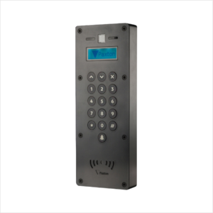
PAXTON ENTRY STANDARD PANEL – SURFACE MOUNT
Entry is a door entry system that works standalone or alongside Paxton’s Net2 access control or Paxton10, access control and video management, combining door entry with key features of our access control software. The Entry standard panel is a robust external panel for use with Paxton’s door entry system, Entry. This panel comes in industry recognised anthracite grey (RAL7021), meaning it complements the windows and doors of many new builds and modern apartments.
-
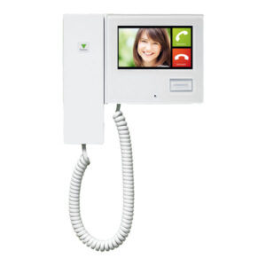
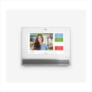
PAXTON NET2 ENTRY MONITOR
- Intuitive, colour touchscreen monitor
- Easy plug and play expansion for large systems
- Smart, simple audio/video door entry
- Units auto detect on setup for straightforward installation
-
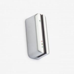
PAXTON CARDLOCK READER – SATIN CHROME
CARDLOCK readers are for use with Switch2 and Net2 systems.
Works with Net2 or Switch2Satin chrome finishLow cost cardsIPX7 rated – suitable for external use -
Entry monitor – desktop stand | Sales Code: 337-294-EX
Adjustable screen angleQuick and simple installation₦ 70.00₦ 99.00Entry monitor – desktop stand | Sales Code: 337-294-EX
₦ 70.00₦ 99.00 -
Gent S4-34895 Surface Back Box (Red) for S4-34800 Range of MCPs
Gent S4-34895 Surface Back Box (Red) for S4-34800 Range of MCPs –
The S4-34895 is a surface mounted call point backbox which has been designed for use with the Gent Vigilon range of manual call points
₦ 500.00₦ 1,000.00Gent S4-34895 Surface Back Box (Red) for S4-34800 Range of MCPs
₦ 500.00₦ 1,000.00 -
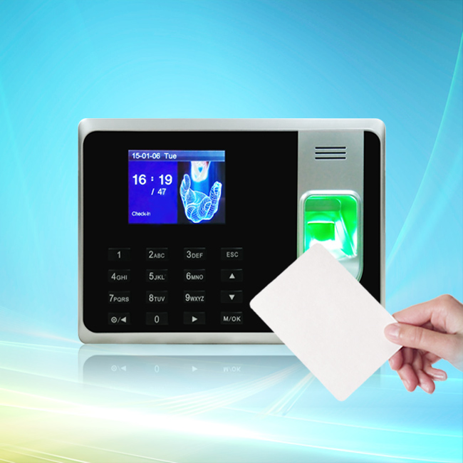
Epordo Proximity Card – Enhance Access Control
✅ High-frequency RFID technology for quick and accurate identification
✅ Durable and lightweight — built to withstand daily use
✅ Compatible with most RFID access control systems
✅ Ideal for offices, hotels, schools, and gated estates
✅ Customizable and easily programmablePerfect for businesses and institutions looking to improve entry efficiency and reduce unauthorized access.
₦ 1,050.00₦ 1,100.00Epordo Proximity Card – Enhance Access Control
₦ 1,050.00₦ 1,100.00 -
N95 Face Mask
Specifications
* Filtration Efficiency: ≥95%
* Material: Non-woven Fabric + Melt-blown Filter Layer
* Type: Foldable / Cup Style
* Color: White / Gray / Black (varies by stock)
* Certification: NIOSH / CE / FDA Compliant₦ 1,050.00₦ 1,100.00N95 Face Mask
₦ 1,050.00₦ 1,100.00 -
Apollo XPERT Card for Base – Precision Configuration5
✅ Quick and secure installation
✅ Compatible with Apollo XP95 & Discovery series
✅ Durable, reliable & engineered for long-term use
✅ Ideal for professional fire alarm setupsAvailable now at Trends Ventures Limited – your trusted distributor of fire safety solutions in Nigeria.
₦ 1,260.00₦ 1,320.00Apollo XPERT Card for Base – Precision Configuration5
₦ 1,260.00₦ 1,320.00 -

Zeta Fyreye Common Base (FE-CB)
DESCRIPTION
Fyreye Common Base
There are 6 Fyerey detector bases available for the conventional range of detectors, namely common base, diode base and relay base.
The Common base is used on systems that don’t need to keep line integrity on head removal, and also on addressable systems.
₦ 1,500.00Zeta Fyreye Common Base (FE-CB)
₦ 1,500.00 -
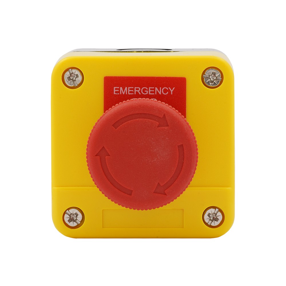
🛑 Emergency Panic Button – Alert security or emergency services
✅ Easy to install
✅ Fast response system
✅ Ideal for banks, schools, hospitals, and personal safetyYour safety is just one button away — dependable, discreet, and life-saving.
₦ 2,100.00₦ 2,200.00🛑 Emergency Panic Button – Alert security or emergency services
₦ 2,100.00₦ 2,200.00 -
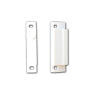
DOOR AND WINDOW SENSOR
Stay one step ahead of intruders and enhance your home or office security with Trends Ventures Limited’s advanced Door and Window Sensor. Designed for smart living, this compact yet powerful device instantly alerts you when any entry point is opened — giving you peace of mind whether you’re home or away.
✅ Real-Time Alerts to your smartphone
✅ Easy Installation — No tools or wiring needed
✅ Works seamlessly with your existing alarm system
✅ Energy-efficient with long-lasting battery life
✅ Ideal for homes, offices, shops, and warehousesWhether you’re securing your front door or monitoring a back window, this sensor is your silent, reliable guard.
Trust Trends Ventures Limited — your partner in smart safety solutions.
₦ 2,500.00₦ 3,000.00DOOR AND WINDOW SENSOR
₦ 2,500.00₦ 3,000.00